

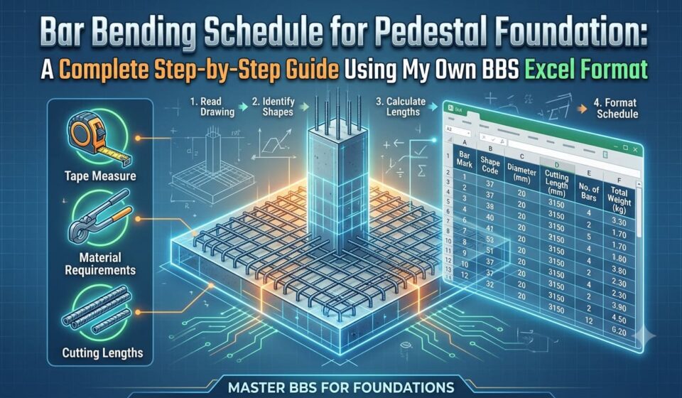
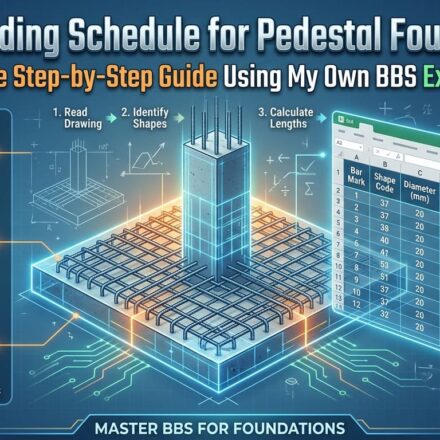
Bar Bending Schedule for Pedestal Foundation: Step-by-Step Guide Using My Own BBS Excel Format

Introduction
Pedestal foundations are one of the most common foundation types you will find on industrial, warehouse, and steel-structure projects. anywhere a structural steel column needs to sit on anchor bolts rather than being cast monolithically with the footing.
The footing does the job of transferring load safely into the soil; the pedestal is the short-reinforced concrete “stub column” that rises from the footing up to the finished floor or plinth level, carrying the anchor bolt cage that the base plate of the steel column ultimately bolts onto.
Preparing a Bar Bending Schedule for Pedestal Foundation is slightly more involved than a plain isolated footing, because you are really scheduling two connected elements in one continuous exercise, the footing mat reinforcement and the pedestal’s vertical bars and ties and the two have to be detailed so that the vertical bars from the pedestal properly anchor down into the footing.
This article walks through exactly how I prepare a BBS for a pedestal foundation, using my own Excel format. the same one I use on live projects and a real worked example built directly off a structural drawing set: general notes, a pedestal reinforcement detail (plan and section), a footing reinforcement plan, and a foundation section.
By the end of this guide you will be able to read a pedestal foundation drawing correctly, set up the exact same BBS Excel format I use, understand every formula behind every column, and calculate a fully correct steel quantity in kilograms and then converted into metric tonnes for a pedestal foundation of your own.
What Is a Pedestal Foundation, and Why Does Its BBS Need Special Attention?
A pedestal foundation consists of two parts cast (usually) in one continuous pour: a spread/isolated footing that transfers load into the soil, and a pedestal, a short reinforced concrete column stub that rises from the top of the footing up to the underside of the base plate, where a steel column will eventually be bolted down using anchor bolts embedded in the pedestal.
You will recognize a pedestal foundation drawing by a few unmistakable features:
- An anchor bolt group (commonly 4, 6, or 8 bolts) shown in a plan view at the top of the pedestal, with bolt spacing dimensions and a grade callout (for example, Grade 4.6 anchor bolts).
- A pedestal cross-section (for example 550 mm X 350 mm) with its own set of vertical main bars and closed ties/stirrups, detailed independently from the footing mat below it.
- A section view through the full depth of the foundation, showing the footing thickness, the pedestal height, and the various ground levels (paved level, finished ground level, and founding level) that the excavation and backfilling must respect.
- A footing reinforcement plan, usually a separate sheet or half of the same sheet, showing the bottom mat bars in both directions and the pedestal’s outline superimposed at the center.
The reason a pedestal foundation deserves special BBS attention is that it is really two BBS problems stacked together, and a mistake in either one has consequences for the other:

If the footing bar count or spacing is wrong, the pedestal’s vertical bars which typically bend into the footing to anchor themselves against the bottom mat will not align properly with the mat, causing a rebar clash at the very bottom of the pour.
If the pedestal vertical bar’s cutting length is wrong, either the anchor bolt cage floats too high (insufficient reinforcement below it) or the vertical bars protrude above the top of grout level, fouling the base plate installation.
If the tie/stirrup spacing is wrong, the pedestal which is often a slender, unsupported element standing several meters above the footing before backfilling is complete can be vulnerable to buckling of the vertical bars during handling and construction, quite apart from any code compliance issue.
Because of this “two elements, one continuous BBS” nature, I always treat a pedestal foundation as one structure with four bar groups footing bottom bars in one direction, footing bottom bars in the perpendicular direction, pedestal vertical bars, and pedestal ties. Every one of these four groups gets its own row (or, in my format, its own small block of rows) in the same BBS sheet, so that the total steel weight for one complete pedestal foundation unit is always visible as a single, addable number.
Where you will typically encounter pedestal foundations?
In my experience, pedestal foundations show up most often on three kinds of projects: pre-engineered steel building (PEB) warehouses and factory sheds, where every structural steel column bolts down onto its own pedestal rather than being embedded in concrete; process and petrochemical plants, where equipment and pipe-rack columns are almost always steel sections on bolted pedestals for ease of alignment and future replacement; and any structure where a steel column needs to be raised above finished floor level for corrosion protection, flood protection, or simply architectural clearance.
If you are a student who has only worked through RCC-column examples so far, think of a pedestal as the reinforced concrete “adapter” that lets a bolted steel column sit safely and correctly aligned on top of an ordinary RCC footing.
It’s also worth noting, before we go further, that the same overall BBS discipline described in this article read the drawing fully, note every cover and spacing value, build the sheet with input cells rather than hardcoded numbers, and cross-check every diameter against the reference table applies regardless of whether the pedestal supports a steel column, a precast concrete column, or a piece of static equipment. The worked example in this article uses a steel-column pedestal (evident from the anchor bolt group and base-plate detail), but the underlying BBS technique is identical either way.
Reading the Drawing Set Before You Touch Excel
Before opening Excel, I always extract every relevant number from the drawing set and write it down in one place. Here is exactly what I pulled from the drawing set for this worked example, and why each note matters to the BBS.
From the General Notes sheet
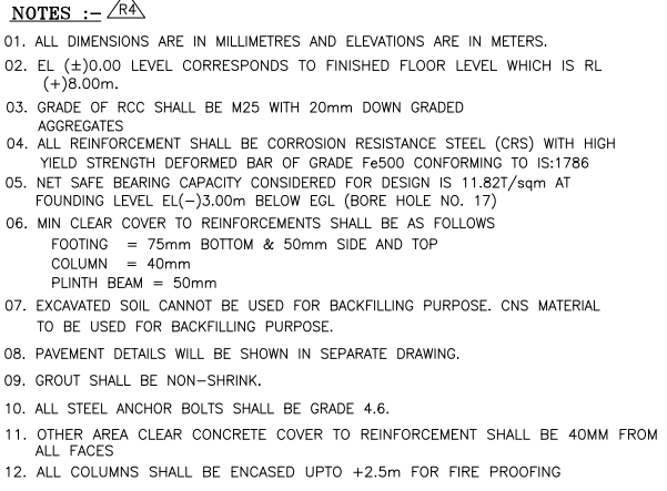
- All dimensions are in millimeters, and all elevations are in meters. this single note is why every BBS calculation below is done in millimeters and only converted to meters at the very last step (Total Cut Length column), exactly the way the drawing itself is dimensioned.
- Finished floor level EL (±)0.00 corresponds to RL (+)8.00 m useful for site-level coordination, though it does not directly affect the BBS quantities themselves.
- Concrete grade is M25 with 20 mm downgraded aggregate, and all reinforcement is Corrosion Resistance Steel (CRS), high yield strength deformed bar of Grade Fe500 conforming to IS:1786. The grade of steel (Fe500) does not change the unit-weight formula weight is a function of geometry and density, not yield strength but it is essential information for the billing engineer when raising the steel purchase order, since Fe500 CRS bars are priced differently from ordinary Fe500 bars.
- Minimum clear cover to reinforcement: Footing = 75 mm bottom & 50 mm side and top; Column = 40 mm; Plinth beam = 50 mm. This note is the most important input for our BBS, because it tells us exactly which cover value to deduct at every edge of the footing (75 mm at the bottom face, 50 mm at the side faces and top face) and exactly which cover to use for the pedestal, which is detailed as a column (40 mm).
- Other-area clear cover to reinforcement shall be 40 mm from all faces, and all columns shall be encased up to +2.5 m for fireproofing general project notes that do not change this specific foundation’s BBS.
From the pedestal plan and section (Views K1-K1, K-K)
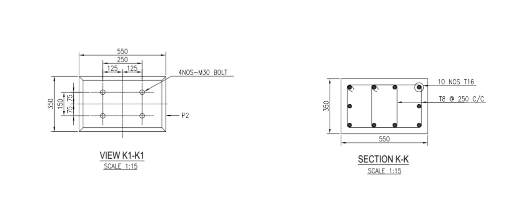
- The pedestal P2 measures 550 mm X 350 mm in cross-section.
- The pedestal’s own reinforcement is 10 Nos T16 vertical bars, with T8 ties at 250 mm center to center enclosing them.
From the footing reinforcement plan (FTG-8)
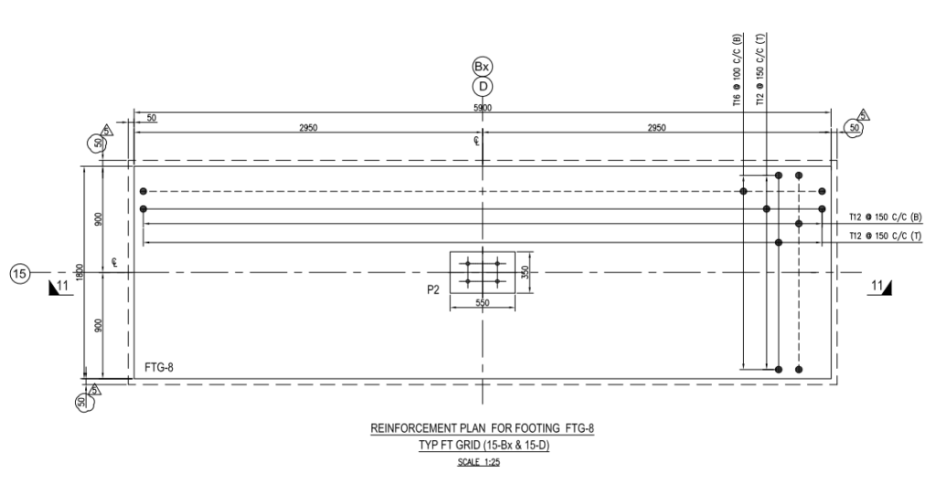
- The footing measures 5000 mm X 1800 mm in plan.
- Bottom bars are T16 at 100 mm center to center in long and other direction Bottom bars are T12 at 150 mm center to center
- Top bars are T12 at 150 mm center to center in both direction
From the foundation section (Section 11-11)
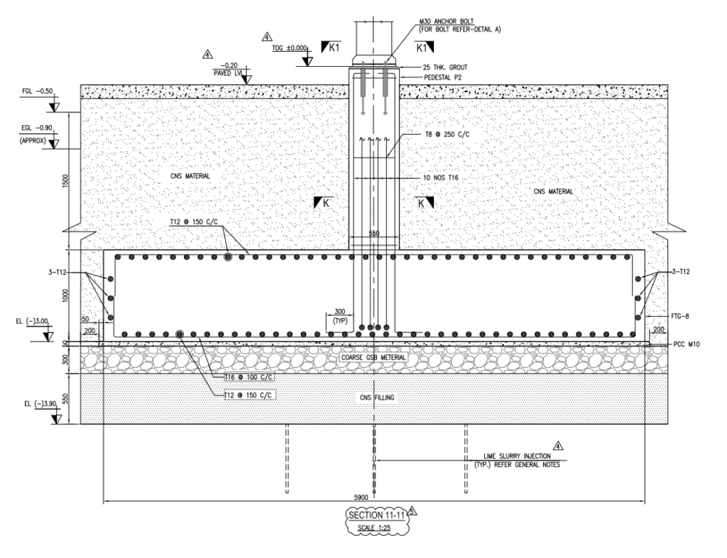
- The footing thickness is 1000 mm.
- The pedestal rises from the top of the footing (3.00, the founding level) up to the top of grout (TOG (+)0.000), giving a pedestal height of exactly 3.000 m.
- With every one of these numbers written down, I am now ready to open Excel and set up the BBS exactly the way I always do.
A quick note on lap splices for large footings
Reinforcement bars are manufactured and supplied in standard stock lengths most commonly around 12 meters. The appropriate lap length as specified in the drawing’s general notes, often expressed as a multiple of the bar diameter, such as 50d.
BBS Excel Format for Pedestal Foundations Column by Column
Unlike a simple 11-column BBS, the format I actually use on site splits the final weight across one column per bar diameter rather than a single “Total Weight” column. I will explain why in Section 7 but first, here is every column, left to right, exactly as it appears on my sheet.
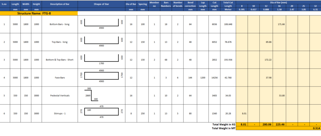
- Sr. No. – Running serial number for the bar
- Length – The overall length (mm) of the structural member this bar group.
- Width – The overall width (mm) of the member
- Height – The overall height/depth (mm) of the member
- Description of Bar – A clear label identifying exactly which bar group this row represents
- Shape of Bar – A small working area where I lay out the individual bar’s shap.
- Dia of Bar – The bar diameter in millimeters.
- Spacing – The center-to-center spacing (mm) between bars
- Member No – How many identical instances of this member exist on the project
- Bars Number – The calculated number of bars in this group
- Number of Bends – How many 90° bends this bar shape involves
- Bend Correction – The total length deducted from the bar’s straight length
- Lap Length – Any additional length added for Lap
- Cut Length – The final straight length the bar must be cut
- Total Cut Length – Cut Length, Bars Number, converted from millimeters to meters.
- Weight columns, one per standard diameter (8, 10, 12, 16, 20, 25, 32 mm). Each of these seven columns checks whether this row’s own diameter matches that column’s diameter header; if it matches, it multiplies Total Cut Length by the correct kg/m unit weight for that diameter and displays the result; if it doesn’t match, the cell is left blank
- Total Weight in KG (bottom row) – The column-wise sum of every diameter column, giving a diameter-by-diameter breakdown of the project’s total steel weight.
- Total Weight in MT – The grand total across every diameter column in metric tons.
- A small reference table sits above the main sheet, listing the standard unit weight (kg/m) for each of the seven diameters used across the weight-matrix columns 0.395 kg/m for 8 mm, 0.617 kg/m for 10 mm, 0.888 kg/m for 12 mm, 1.58 kg/m for 16 mm, 2.47 kg/m for 20 mm, 3.85 kg/m for 25 mm, and 6.31 kg/m for 32 mm.
The Critical Excel Formulas Behind Every Column
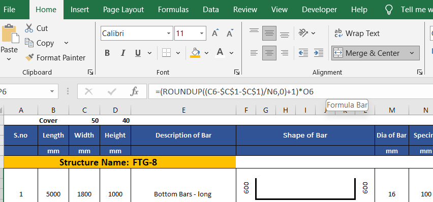
Bars Number: = (ROUNDUP ((Perpendicular Dimension – Cover – Cover)/Spacing, 0) +1
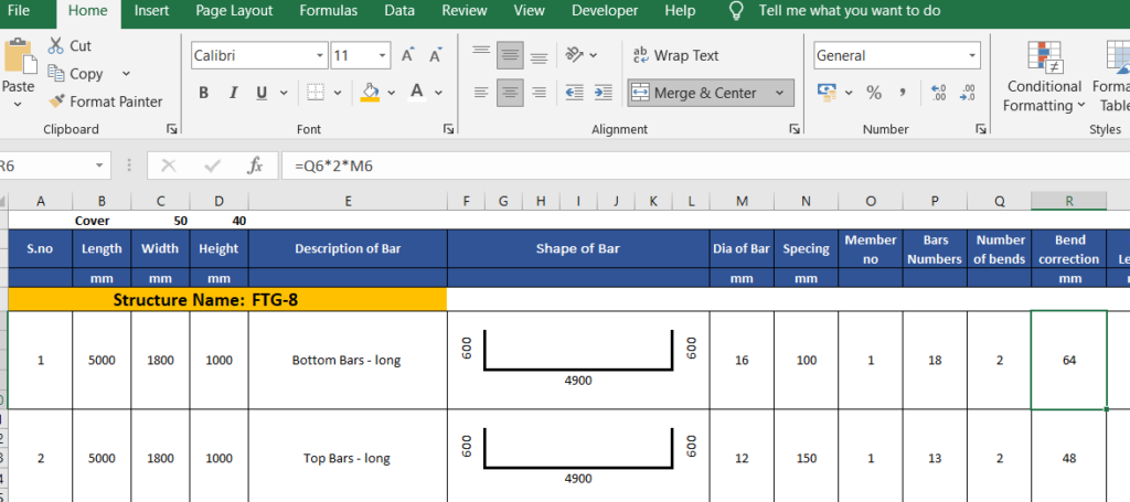
Number of Bends and Bend Correction: =Number of Bends*2*Diameter
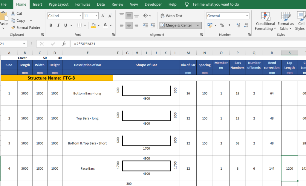
Lap Length: =2*50*Diameter
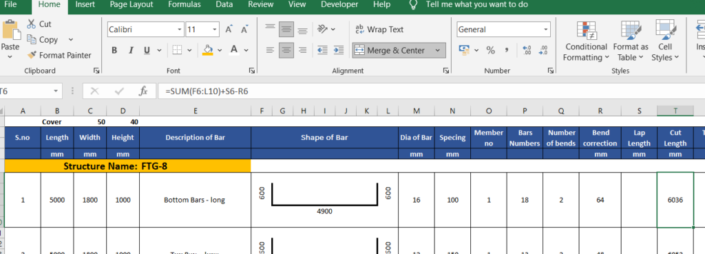
Cut Length: =SUM (Shape Segment Cells) + Lap Length – Bend Correction
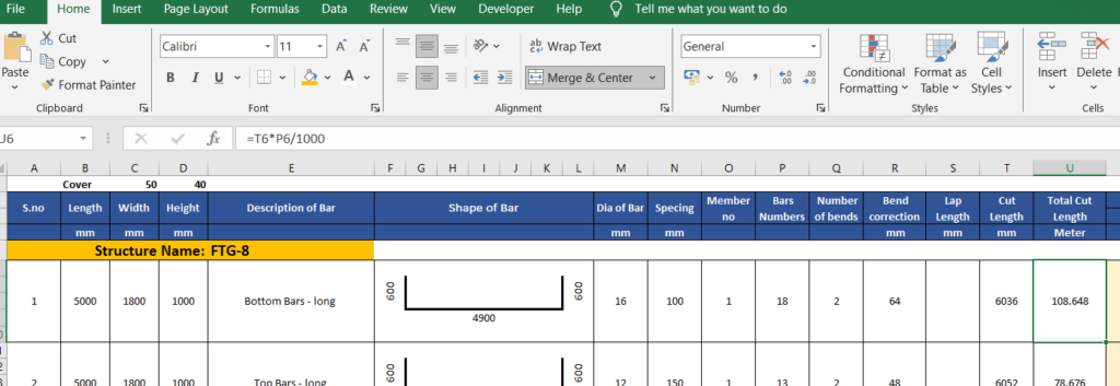
Total Cut Length: =Cut Length*Bars Number/1000
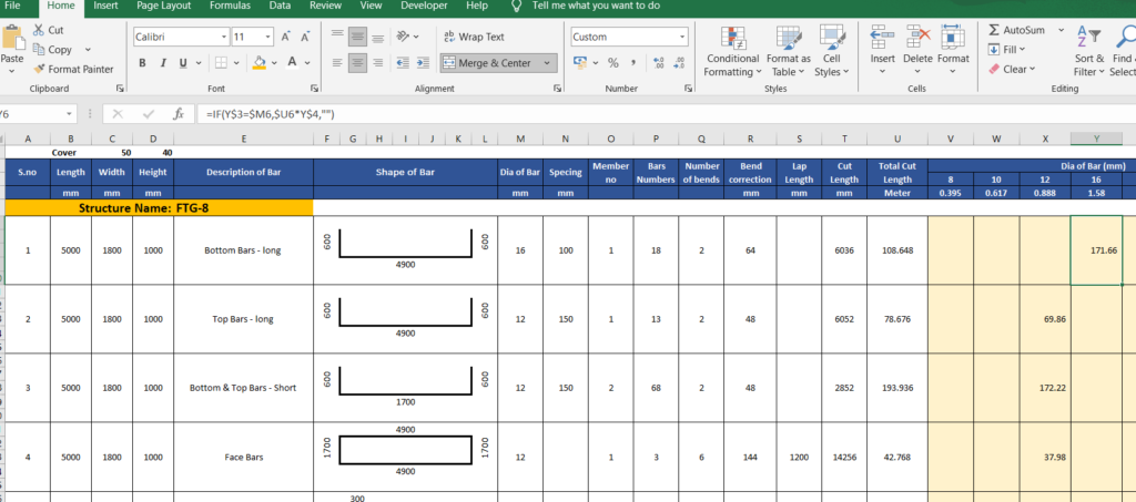
The Per-Diameter Weight Columns: =IF (Dia Header Cell = Row Diameter, Total Cut Length * Unit Weight for This Diameter, “”)
- otal Weight in KG: =SUM (Entire Column Range)
- Total Weight in MT: =SUM (All Diameter Column Totals)/1000
- For this sample excel BBS sheet, you can comment on this blog. i will share to you directly in DM
Now let’s run every formula above against the real drawing data for footing FTG8 carrying pedestal P2.
Full Worked Example: Footing FTG-8 with Pedestal P2
- Footing size (Length, Width, Thickness) 5000 mm 1800 mm 1000 mm
- Footing bottom cover 75 mm, side/top cover 50 mm
- Footing bottom bars, long directions T16 @ 100 mm c/c, Short T12@ 150 mm c/c
- Footing top bars, both directions T12@ 150 mm c/c
- Pedestal size 550 mm X 350 mm
- Pedestal height (footing top to top of grout) 3000 mm
- Pedestal cover (column) 40 mm
- Pedestal vertical bars 10 Nos T16
- Pedestal ties T8 @ 250 mm c/c
Bar Group 1: Footing Bottom Bars Long Direction
Bars Number: Clear span (width) = 1800 – (2 x 50) = 1700 mm
Bars Number = ROUNDUP (1700 / 100, 0) + 1 = 17 + 1 = 18 bars
Bend Correction: Number of Bends = 2, and Bend Correction = 2 x 16 x 2 = 64mm
Cut Length = Length – (2 x side cover) + two side L length – bend correction = 5000 – (2 x 50) + 2 x ((1000 – (2 x 50) / 2) + 150 – 64 = 6036 mm
Total Cut Length = 6036 x 18 / 1000 = 108.648 m
Weight (16 mm x 1.58 kg/m): Weight = 108.648 x 1.58 = 171.66 kg
Bar Group 2: Footing Top Bars Long Direction
Bars Number: Clear span (width) = 1800 – (2 x 50) = 1700 mm
Bars Number = ROUNDUP (1700 / 150, 0) + 1 = 12 + 1 = 13 bars
Bend Correction: Number of Bends = 2, and Bend Correction = 2 x 12 x 2 = 48mm
Cut Length = Length – (2 x side cover) + two side L length – Bend correction = 5000 – (2 x 50) + 2 x ((1000 – (2 x 50) / 2) + 150 – 48 = 6052 mm
Total Cut Length = 6052 x 13 / 1000 = 78.676 m
Weight (12 mm x 0.888 kg/m): Weight = 78.676 x 0.888 = 69.86 kg

Bar Group 3: Footing Bottom & Top Bars Short Direction
Bars Number: Clear span (length) = 5000 – (2 x 50) = 4900 mm
Bars Number = 2 x ROUNDUP (4900 / 150, 0) + 1 = 67 + 1 = 68 bars
Bend Correction: Number of Bends = 2, and Bend Correction = 2 x 12 x 2 = 48mm
Cut Length: Length – (2 x side cover) + two side L length – bend correction = 1800 – (2 x 50) + 2 x ((1000 – (2 x 50) / 2) + 150 – 48 = 2852 mm
Total Cut Length = 2852 x 68 / 1000 = 193.936 m
Weight (12 mm x 0.888 kg/m): Weight = 193.936 x 0.888 = 172.22 kg
Bar Group 4: Footing Face Bars
Bars Number = 3 bars
Bend Correction: Number of Bends = 2, and Bend Correction = 3 x 12 x 2 = 72 mm
Cut Length: Length – =2 x (length of Long side + Short side) + two x Lap length – bend correction = 2 x (1800 + 5000 – (4 x 50)) + 2 x 50 x 12 + 150 – 72 = 14256 mm
Total Cut Length = 14256 x 3 / 1000 = 42.768 m
Weight (12 mm x 0.888 kg/m): Weight = 42.768 x 0.888 = 37.98 kg
Bar Group 5: Pedestal Verticals (10 Nos T16)
Foot / anchorage leg into the footing = 300 mm
Straight run through the pedestal height = Height – bottom cover – bar diameter – grout thickness – column cover = 3000 – 50 – 16 – 25 – 40 = 2869 mm
Top allowance (below anchor bolt cage) = 300 mm
Bend Correction: Number of Bends = 2, and Bend Correction = 2 x 16 x 2 = 64 mm
Cut Length = 300 + 2869 + 300 – 64 = 3405 mm
Bars Number: 10 (directly specified on the pedestal section, no spacing calculation needed).
Total Cut Length: Total Cut Length = 3405 x 10 / 1000 = 34.05 m
Weight (16 mm x 1.58 kg/m): Weight = 34.05 x 1.58 = 53.80 kg
Bar Group 6: Pedestal Ties / Stirrups (T8 @ 250 mm c/c)
Bars Number: Bars Number = ROUNDUP (2844 / 250, 0) + 1 = 12 + 1 = 13 ties
Shape of the tie: A closed rectangular tie wrapping the 550 mm x 350 mm pedestal cross-section, with the standard clear cover of 40 mm on every face:
Leg 1 (along 550 mm side, less cover both ends) = 550 – (2 x 40) = 470 mm
Leg 2 (along 350 mm side, less cover both ends) = 350 – (2 x 40) = 270 mm
Sum of the four legs = (470 x 2) + (270 x 2) = 940 + 540 = 1480 mm
Hook Length: 2 x 10 x diameter of stirrups = 2 x 10 x 8 = 160 mm
Lap Length = 2 x 50 x 8 = 800 mm
Number of Bends = 5 (3 corner bends of the rectangle + 2 hook-end bends where the tie closes on itself).
Bend Correction = 5 x 2 x 8 = 80 mm
Cut Length = 1480 + 160 – 80 = 1560 mm
Total Cut Length = 1560 x 13 / 1000 = 20.28 m
Weight (8 mm x 0.395 kg/m): Weight = 20.28 x 0.395 = 8.01 kg
Complete BBS summary for one FTG-8 + P2 pedestal foundation unit
Total weight, T8 (8 mm) bars: 8.01 kg
Total weight, T12 (12 mm) bars: 280.06 kg
Total weight, T16 (16 mm) bars: 225.46 kg
Grand total for one complete pedestal foundation unit: 514kg
Converting Total Steel Weight into Metric Tones
1 Metric Tone = 1000 Kilograms
Total Weight (MT) = Total Weight (KG) / 1000 = 514 / 1000 = 0.51 MT
This is the steel requirement for one pedestal foundation of this exact type
As with any BBS, I always add a small wastage allowance typically 2.5% on top of the theoretical total before the final purchase order is raised, to account for cutting losses and minor site rejections.
Why I Split Weight by Diameter Instead of Using One Total Weight Column
A single “Total Weight” column, summed at the bottom of the sheet, tells you the overall tonnage of steel a project needs useful for a high-level budget figure, but not directly useful for actually placing an order with a steel supplier or mill. Steel is never ordered as an undifferentiated tonnage; it is ordered by diameter, because different diameters come as different products with different unit prices, different minimum order quantities, and often different delivery lead times.
By giving each standard diameter (8, 10, 12, 16, 20, 25, 32 mm) its own column, and letting a simple `IF` formula route each row’s weight into the correct column automatically, my sheet does the diameter wise segregation for me as a natural byproduct of the BBS calculation itself. I never have to manually filter or pivot the data afterward. The moment I finish entering a new bar group, its weight is already sitting in the right diameter column, and the column totals at the bottom of the sheet are, at all times, a live, accurate, diameter-wise purchase list.
Common Mistakes Specific to Pedestal Foundation BBS
Beyond the general BBS mistakes covered in earlier articles in this series, a pedestal foundation brings its own specific failure points:
- Forgetting that the pedestal uses a different cover than the footing
- Treating the pedestal vertical bar as a simple straight length equal to the pedestal height.
- Forgetting the tie/stirrup count depends on the reduced straight height, not the full pedestal height.
- Mixing up the tie’s two leg dimensions. A rectangular pedestal
- Including the anchor bolts as a BBS line item.
- Forgetting to update the Member No column when the same pedestal type repeats across the grid.
- Assuming every pedestal on a project is identical without checking the anchor bolt group.
Frequently Asked Questions (FAQ)
Q1. What is the difference between a pedestal foundation and a plain isolated footing?
A plain isolated footing supports a reinforced concrete column that is cast monolithically with (or directly onto) the footing. A pedestal foundation instead carries a short reinforced concrete stub the pedestal that rises from the footing to support a bolted base plate, typically for a structural steel column, using an anchor bolt group embedded in the pedestal.
Q2. Why does the pedestal vertical bar need a foot/bend into the footing instead of just resting on top of it?
A straight bar resting flat on the footing’s bottom mat, without any bend or sufficient embedment, would not develop adequate bond and anchorage into the concrete. Bending the bar’s end into a short foot increases its anchorage value within the limited footing depth available, ensuring the load path from the pedestal into the footing (and ultimately into the soil) is properly maintained.
Q3. Are anchor bolts included in the Bar Bending Schedule?
No. Anchor bolts are structural steel hardware, typically of a specific bolt grade (Grade 4.6 in this example), procured and billed entirely separately from reinforcement steel. They do not use the reinforcement unit-weight formula and should never appear as a weighted line item inside your BBS.
Q4. Why are the footing bottom cover (75 mm) and the pedestal cover (40 mm) different in this drawing?
The footing’s bottom face is cast directly against the ground (via a PCC/blinding layer), where soil contact, moisture, and potential ground contamination justify a larger, more conservative cover requirement. The pedestal, by contrast, is essentially a column cast within formwork above ground, in a controlled environment much closer to typical column-casting conditions so it follows the smaller, standard column cover instead.
Q5. Why does the number of ties depend on a “reduced” height rather than the full pedestal height?
Ties are only required to confine the reinforced, load-bearing straight portion of the pedestal, between the top and bottom cover-related transition zones. The full outside-to-outside pedestal height (3000 mm in this example) includes small allowances at both ends for cover and bar transition that are not part of the zone ties are meant to confine, so the tie count formula uses the reduced, “tie-able” height instead.
Q6. Can the same diameter-column BBS format be used for elements other than pedestal foundations?
Yes, this exact format (Length/Width/Height inputs, a shape-segment working area, bend correction, lap length, and a diameter-wise weight matrix) works identically for columns, beams, slabs, or any other reinforced concrete element. Only the specific shape-segment values and bend/tie conventions change from element to element; the underlying spreadsheet mechanics stay the same.
Q7. How do I handle a project where several footing marks share the same pedestal type but different footing sizes?
Calculate the shared pedestal type’s vertical bars and ties exactly once, and re-use those same rows unchanged across every footing mark that uses that pedestal only the footing-specific bottom-mat rows need to be recalculated with each footing mark’s own plan dimensions, as described in Section 10.
Q8. Does the concrete grade (M25 in this example) affect any part of the BBS calculation?
No. Concrete grade determines the strength and mix design of the concrete itself and, indirectly through the structural design, the bar sizes and spacings the engineer specifies but it does not enter any BBS formula directly. Once the bar diameter, spacing, and cover are fixed on the drawing, the BBS calculation is identical regardless of whether the surrounding concrete is M20, M25, or M30.
Q9. Why does the drawing specify Fe500 CRS bars specifically, and does that change the unit weight formula?
Fe500 refers to the bar’s minimum yield strength (500 N/mm²), and CRS (Corrosion Resistance Steel) refers to an enhanced corrosion-resistant chemistry, often specified for foundations exposed to aggressive soil or groundwater conditions. Neither of these properties changes the physical density of the steel in any meaningful way for BBS purposes, so the same diameter-squared-over-162.2 unit weight formula applies regardless of the specific grade or corrosion-resistance rating grade and corrosion class matter for billing and material certification, not for the weight calculation itself.
Q10. Should the pedestal’s vertical bars and the footing’s bottom mat bars ever be tied together as one continuous bar instead of two separate bar groups?
In almost all practical detailing, no the footing mat is a distinct, closely spaced two-way mesh serving the footing’s own bending behavior, while the pedestal verticals serve an entirely different structural function (transferring the column load down through the pedestal). They are detailed, scheduled, and fabricated as separate bar groups that simply sit close to one another and are tied together on site for stability during the pour, rather than being one single continuous bar bent through both elements.
Conclusion
A pedestal foundation’s Bar Bending Schedule is best understood not as a single calculation, but as two connected calculations, the footing mat and the pedestal’s own reinforcement brought together in one BBS sheet so that the true steel requirement for one complete foundation unit is always visible as a single number. The formulas themselves are nothing more than the same clear-span, bend-correction, and unit-weight principles that apply to any reinforced concrete element; what changes with a pedestal foundation is simply the care needed in tracking two different cover values, in correctly deriving the pedestal vertical bar’s foot/anchorage length, and in basing the tie count on the pedestal’s tie-able height rather than its full outside dimension.
Once you have worked through this example by hand footing bottom bars in both directions, pedestal verticals with their anchorage foot, and pedestal ties on their reduced tie-able height you have every tool you need to build the same diameter-segregated BBS format for any pedestal foundation drawing that lands on your desk, and to hand your billing engineer a diameter-wise steel quantity that is ready to become a purchase order without any further manual work.
For More Blogs click the link below………………..>>>
Mastering RA Billing Preparation in Construction: A Complete, Step-by-Step Guide for Contractors
RA Bill Checking: Complete Audit accomplished Framework for Civil Engineers

No Inspection, No Measurement, No Payment: The Quality Papers Behind Every RA Bill in a Mumbai Project
A site engineer’s practical guide to the documents that make an RA bill stand up…
M30 on the Drawing, Honeycomb on the Column: What Really Decides Concrete Quality
A civil engineer’s practical guide to concrete, built around IS Code, can answer this simple…

Mastering Reinforcement Steel Reconciliation: A Technical Blueprint for Civil Engineers & Project Managers
1. Executive Summary & Introduction In structural concrete construction, reinforcement steel Reconciliation represents between 20%…
20 Essential Technical Interview Questions (Part – 3) | Master Class in Construction Project Billing & Quantity Surveying
I’ve sat on both sides of the table for these Technical interviews as the guy…
Steel Reconciliation Format in Construction | The Most Misunderstood Document in Project Billing, Cost Control and Technical Audits
Excel Reconciliation Format Download here There are a few documents like Steel Reconciliation Format in…

Complete Guide Work Order Understanding | Beyond The BOQ: How A Billing Engineer Must Read Every Line Of A Work Order (Part 2)
I still remember one particular bill audit many years ago. Work Order Understanding was the…















Dear sir
Please send me the BBS sheet
Yes, will share to your email id.
Thank you