
Bar Bending Schedule Essentials: Common Errors and Practical Insights for Civil Engineering should help your Knowledge in 2026
Understanding Unit Weight Error of Reinforcement Steel in Civil Engineering
In civil engineering, precision in calculation is vital for accurate estimation and billing. One common area where minor discrepancies occur is in the unit weight of reinforcement steel.
Standard Formula for Unit Weight
Engineers often use the standard formula:
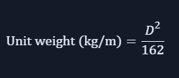
This formula is technically correct and widely accepted for on‑site calculations and estimation. It provides a quick and reliable way to determine the weight of steel bars based on their diameter.
Example Calculation
Let’s consider a 25 mm diameter reinforcement bar.
Using the formula:

However, according to the Indian Standard (IS) code tables, the unit weight of a 25 mm steel bar is 3.85 kg/m.
This shows a minor difference of about 0.01 kg/m, which occurs due to rounding‑off and standardization in IS code values.
Why the Difference Matters
While this variation is negligible for small quantities, it can become significant in large‑scale projects or bulk steel procurement.
Following IS‑specified unit weights ensures:
- Better accuracy in billing and auditing
- Compliance with standard codes
- Consistency across project documentation
Clear Cover vs Nominal Cover in Civil Engineering
In reinforced concrete design, understanding the difference between clear cover and nominal cover is essential for ensuring durability, safety, and compliance with design standards.
Clear Cover in Civil Engineering
Clear cover refers to the actual measured distance between the outer surface of concrete and the nearest surface of reinforcement steel including main bars, stirrups, or ties.
It represents the physical cover achieved at site and is verified during execution using cover blocks and on‑site measurements.
Nominal Cover in Civil Engineering
Nominal cover, on the other hand, is the design‑specified value of cover.
It includes allowances for construction tolerances and ensures:
- Required durability
- Fire resistance
- Protection against corrosion
Nominal cover is most commonly specified in design documents and is considered the distance between the concrete surface and the main reinforcement steel.
Example Illustration
- In the diagram below:
- Clear Cover: 40 mm
- Nominal Cover: 50 mm
- Main Bar: 25 mm diameter
- Stirrups: 10 mm diameter
This visual distinction helps engineers understand how design values differ slightly from actual site measurements — a crucial detail for maintaining long‑term structural integrity.

Engineering Insight
While clear cover ensures physical protection on site, nominal cover guarantees design compliance and performance throughout the structure’s service life.
Both must be carefully considered during design and execution to achieve the desired balance between strength, durability, and safety.
Calculation of Number of Reinforcement Bars (Rounding Concept)
When calculating the number of reinforcement bars required for a given area, engineers often use mathematical functions such as round or round‑up.
However, it’s crucial to remember that for reinforcement detailing, the number of bars must always be rounded up.
Why Round‑Up Is Mandatory
Under no circumstances should under‑provision or a lesser quantity of reinforcement be allowed compared to design or drawing requirements. Doing so leads to non‑compliance and possible rejection by the design consultant.
Key reasons for rounding up:
- Reinforcement spacing in drawings represents the maximum allowable spacing.
- Providing fewer bars increases spacing beyond the permitted limit.
- Structural design does not permit under‑reinforcement.
- Excess reinforcement (within limits) is acceptable — deficiency is not.
Example for Better Understanding
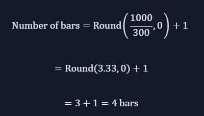
Consider a slab area of 1 m × 1 m, where 12 mm diameter reinforcement bars are placed at 300 mm c/c spacing.
Using the ROUND formula:
This ensures that the spacing remains within design limits and structural integrity is maintained.
Engineering Insight
Always round up reinforcement quantities to meet design intent and safety standards.
Even a single missing bar can compromise spacing, load distribution, and long‑term durability — especially in slabs, beams, and columns.
Observation on Reinforcement Bar Calculation (Round vs Round‑Up)
When calculating reinforcement bars, engineers must ensure that spacing and quantity comply with design standards. The difference between round and round‑up functions can significantly affect structural accuracy and approval.
Observation (Using ROUND Formula)
- Spacing between bars becomes 400 mm
- This exceeds the specified 300 mm c/c spacing
- Hence, this arrangement does not comply with design requirements
- The design consultant will not approve further execution (Refer Fig. 001)
Using ROUND‑UP Formula
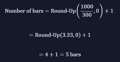
Observation (Using ROUND‑UP Formula)
- Spacing between bars becomes approximately 250 mm
- This is less than the maximum allowable spacing of 300 mm
- Reinforcement quantity is slightly on the higher side
- The arrangement fully complies with design and code requirements
- There will be no objection from the consultant (Refer Fig. 002)
Engineering Insight
Using the ROUND‑UP method ensures that reinforcement spacing remains within permissible limits and meets structural design intent.
While it may slightly increase steel quantity, it guarantees code compliance, safety, and consultant approval all critical for maintaining project integrity.
Development Length (Ld)
In reinforcement design, development length plays a crucial role in ensuring that steel bars are properly anchored within concrete to achieve full strength transfer.
While many engineers apply a single constant development length throughout a structure, this practice is not technically correct and can lead to discrepancies with design intent and code compliance.
Understanding Development Length in Civil Engineering
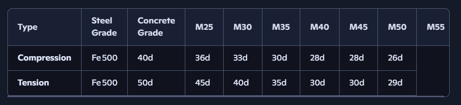
Structural drawings and specifications usually provide development length or lap length values in tabular form, based on parameters such as concrete grade and steel grade.
These values must be applied case‑by‑case, not uniformly across the entire structure.
Where d is the diameter of the reinforcing bar.
Important Factors Affecting Development Length
When determining lap or development length, engineers must consider:
- Grade of concrete
- Grade of reinforcement steel
- Nature of force at the location:
- Tension
- Compression
Ignoring any of these factors can lead to incorrect anchorage length and non‑compliance with structural design codes.
Engineering Insight
Providing slightly higher reinforcement is acceptable, but under‑reinforcement is never permitted.
Accurate development length ensures proper load transfer, prevents bond failure, and maintains structural integrity throughout the service life of the building.
Example for Better Understanding
Let’s consider a situation where there’s a difference in concrete grade between two connected structural elements:
- Stitch Raft concrete grade: M30
- Foundation concrete grade: M35
In this case, reinforcement bars from the stitch raft are anchored into the foundation.
The development length (or lap length) for these bars must be calculated based on the concrete grade of the foundation (M35) – not the stitch raft (M30).
As per Lap Length Tables
- Lap length within M35 concrete = 40d
- Not 45d, which would apply if M30 concrete were considered
Development length depends on the grade of concrete in which the bar is anchored, not the grade from which it originates.
Engineering Insight
This distinction ensures that reinforcement achieves full bond strength and structural continuity.
Applying the correct development length prevents anchorage failure and guarantees compliance with IS 456 and related design codes – a small detail that makes a big difference in long‑term durability.
Nor you can read my Earth work Excavation related article.